Friday 3 May 2024

Rye Field Models RM - 5086 1/35 StuH 42 & StuG. III Ausf G late production


Having recently finished building RFM’s Panzer IV Ausf J and currently still having lots of fun with their Panzer IV Ausf J interior kit, I really fancied tackling another one of their 1/35 armour kits. This year I’ve not started another soft skin, which is what I mainly build, as these kits have just been such a pleasurable experience. The engineering is so good, and the plastic such a similar colour match, that I keep thinking I’m building a Tamya kit😉  


As the end of last year was all about Panzer IVs for me, this year I’m maxing out on StuG’s. Over the last few months, I have Dragon’s lovely StuG III Ausf F8 ready for paint. This will be based on an Italian campaign vehicle as I have some nice period images which capture some unusual features.


I also ‘blitzed’ through Takom’s StuG III Ausf G (Early). This was built straight out of the box with no intention of losing any sleep over its many inaccuracies.


So, as I’m slowly getting to know my way around a Panzer III chassis and many of the later StuG variants, I figured why not check out one of RFM’s StuG's. I choose their Ausf G late kit and it’s a belter. I’ve read there are a few small anomolies but they are minimal and nothing that cannot be easily remedied. According to those knowledgeable on ML, it is the perfect base kit that requires little extra work to portray a decent Alkett built last production Ausf G.


This is the non-interior 2022 released kit 5086 and you can build a StuG III or a StuH42. RFM 5086 info It includes both Alkett and MIAG track guards as it incorporates sprues from their Panzer III as well as from earlier StuG kits. The tracks are RFM’s own individual links which incorporates a jig to complete small runs, speeding up construction. There is no turned metal barrel, but the one-piece slide moulded one provided is easy to clean up. There are two frets of photoetch. The largest covers the Schurzen plates. The wheels incorporate poly caps which I personally like and fit nice and snug just like on many a Tamiya kit.


The lower hull is of flatpack design and fits together perfectly. The torsion bars can be made workable, or you can simply glue the ends onto the lower hull. There is even a choice to build adjustable shock absorbers. Your choice. When it comes to the bow armour the StuG III went through quite a few production design changes in this area. Unlike another certain manufacturer I could mention, the correct parts are called out, even though there are several other variant parts available on the sprues. The running gear lines up really nicely as does all the features on the rear plate. 


The interlocking bow plate portion which would be partly visible just forward of each sprocket on each lower hull side, strangely isn't moulded on. I chiselled out the feature and added the welding marks. The transmission plate is just dry fitted in the image below.


One of the oddities in the kit, is the choice of tracks. The open guide horn type was seen on StuG III's, but the fitment was almost certainly not common. A period image that captured my attention had the more common type, seen on these variants, and as I had a 3D set of T-Rex links, I figured these were the ones to go for. That decision wasn’t one of my best! Unlike three earlier sets which I had a blast with, these were a right PITA. They definitely were not from the same batch as my earlier sets, as the material was far more brittle. I also had far too many links break! To compound the issue the top of the pins did not appear to show any taper, and a significant percentage were already damaged in their small bags! TBH, I thought of contacting the seller but figured, I should at least see if I can build up two complete runs first. I did, but only just, and the pins were falling out as quick as I popped them back in! In the end and after a selection of choice words, I brush painted over the link pin ends with Vallejo grey primer. This seemed to solve the issue, but I then found the links were a tight fit over the sprocket, and I now don't trust them to take much more handling!  


After all the track building issues, I decided to give the kit tracks a go. Also, as RFM only offer the earlier style round tow cable clamps, I ordered the correct square Alkett type from Panzerwerk Design Alkett late tow cable brackets. Whilst postage is way in excess of their cost, I also plumped for some of their Type 6B tracks  Pz.III & IV type 6B links at the same time. They look good and have favourable reviews, so I will build them up when they come, and choose whether they trump the kit tracks later in the build.


As it would give the choice to display the vehicle on uneven ground, I opted to utilise the kit's adjustable torsion bar set up, which work in conjunction with the kit’s optional moveable damper units. Due to the kit's engineering in this area this system naturally allows the wheels to lift over any obstacle beneath them, and the moveable damper units equally compress, but the design does not enable the torsion bars to naturally rebound. This effect is visible in the first image below. The first and last front bogie wheels are slightly affected unnaturally by the kit track tension and are pulled a little higher than they would normally sit on level ground. It’s not really an issue per say, and if displayed on even ground the final position can still be corrected, so it’s nice to have this option.


The T-Rex tracks do look the business, but this set was far from perfect. The track tension on the other side is a touch loser on the image below, so all the bogie wheels sit nice and level.


One construction fix which was pointed out to me by a fellow modeller, involves two strengthening ribs (parts D13 & D14), which you are instructed to add to the undersides of the gun box in step 13. What they do in essence, is create a channel which allows the gun box to align squarely onto both of the thin lower hull side plates. The problem is that they only need to be fixed a fraction off and the channel will become too narrow. To remedy this potential fit issue, you just need to attach the parts directly to the lower hull instead. There are alignment slots in the lower hull side plates too, so it’s a really simple fix.


The lower hull interior includes a fighting compartment floor to which the gun cradle fixing mount is attached. At the rear only the inner two of the four spars that you are instructed to fit between the lower hull back plate to the extension over the exhausts featured on these late production vehicles. It is not an issue to fit them as instructed as they are not visible (unless you are an IPMS/USA judge) and the extension rear plate outer detail has the correct bolt head detail for just the two inner ones that remained.


In step 15 you get to choose your gun type and unlike any earlier manufacturer's releases, each gets its own parts and construction steps. It is worth mentioning that in step 19 it is not at all clear in which order to attach the breech sub-assembly, gun box, lower hull and mantlet all together! I’m sure there are a few ways that folks have managed to do this successfully, but it is not at all obvious and quite a conundrum to figure out.


Breech assembly with added weld detail on the recuperator and an aftermarket barrel. I incorporated the kit's spring so I can leave it adjustable to ensure I end up with the correct length of visible barrel outside of the mantlet.


The full breech sub-assembly with the mantlet and muzzle brake dry fitted.


I’m currently building up the engine deck which comes as a separate moulding but I’m not going to attach all the parts permanently until I can confirm how the Legends Production stowage I have sourced is contoured to fit. 


Engine deck, armoured engine hatches and gun box roof still dry fitted.

The loaders front armour plate provided in the kit is of the earlier production design which incorporated two (50 & 30mm) plates. Late Ausf G had a single 80mm plate. It would be quite easy to hide the join if it were not for the fact that the kit’s outer 30mm plate part does not feature the extra portion that curves down to match the contours of the inner plate. I shaped a similar thickness piece of grey styrene to mimic the outer plate then scribed torch marks over both plates to hide the join. I understand the correct single 80mm plate can be found spare on the sprues of many a Dragon StuG kit.


RFM appear to have used the same gun box moulding as in their early Ausf G kit, so some features require alteration. The instructions do point out the removal of witness marks for the smoke dischargers, and the removal of four rivets on both sides, to enable the fitment of the Schurzen hangers. They don’t however instruct you to fill the four small holes on the rear. These were to enable fitment of the earlier production rear loaders hatch which was re-designed.


Moving onto the engine deck moulding, this fits perfectly onto both the lower hull and against the back of the gun box, and if you wish, can be fixed in place before any further accessories are added. If like me, you prefer to add the most fragile items once the large assemblies are in place, access to all the added parts shown in steps 25 to 27 remain unhindered if you do. 


All the engine hatches come as separate items. Yet another oddity with the instruction sheet is that a small 3D part is to be added just behind the cleaning rods on the rear deck, yet there isn’t one in the kit, nor is it shown in the included parts map! Very odd, as the part shape is both difficult to identify should you wish to scratch a replica, and you are left with a small locating hole on the deck! A more important possible anomaly is the inclusion of diagonally shaped mesh for the engine cooling louvres. Although not conclusively proven it is believed that Alkett produced late Ausf G vehicles were only seen with a square mesh type. Late MIAG vehicles look to have retained the diagonal type, but to muddy the waters further an unmolested museum piece has a combination of both! I don’t think using the kits photo-etched item would be a massive issue, but the square type is available from two aftermarket manufacturers. The kit also includes a multipart photoetch support rail which fits around the outside of the engine deck. As period images showed these vehicles crammed with added stowage and crew gear, I plan to add some aftermarket stowage so that will be tackled at the same time to ensure it all fits together nicely.


As we have seen already, there are a few features that were unique to one or the other of two manufacturers that built the final batch of Ausf G, but unlike MINIART, RFM do not specify which one they are representing. Most features you are instructed to add, do point to an Alkett built vehicle; however, a few others have been confused. If you know what features are particular to each manufacturer then it makes it easier to differentiate, and the inclusion in the kit of almost all the features of both, is a big plus. If depicting an Alkett build, it is worth noting that RFM only include the original round type MIAG installed tow cable brackets. Alkett brackets were a unique square shape and as the kit part is moulded to the tow hooks, they ideally will need to be replaced along with aftermarket copper braided tow cables. Both Modelkasten and Panzerwerk design offer these brackets. Observing the details on the Alkett track guards; the tubular supports are not quite as faithfully represented as they could be. The shape is not quite on the money, but inclusion of photoetch strengthening ribs improve the overall appearance. The rear convoy light RFM provide is not one that either manufacturer fitted. It should be of the tube type design. These can be found as spares in many Panzer kits. I believe RFM’s own Panther have them.


As in their earlier Panzer III and IV kits, RFM have moulded the main part of all the tool brackets to the tools, but the clasps come as photoetch parts. It’s a neat way of keeping the photoetch parts count down, whilst also enhancing the scale appearance of the most prominent feature of the bracket. The inclusion of separate tow clevis brackets in photoetch is also a welcome addition. It is just a single piece but does require careful bending before fixing in place. The clasp is yet to be added in the image below.

As already mentioned, test fitting both the gun breech assembly and the mantlet to the gun box is a tricky affair, but the fitment of part G65 pretty much insures they have to be fixed in place at this point. I wanted to paint the interior, and fixing part G65 as instructed will essentially trap the breech assembly inside, or if not paying attention, outside! A simple fix is to add part G65 to the roof plate (part G110) instead, leaving the roof plate the last part of the gun box to be fixed in place. I sourced a kit specific aftermarket metal barrel, and along with the spring, fixed it to the breech assembly leaving it moveable, so I could paint the whole sub-assembly separately.

The rotating cupola can be built with the small periscope flap open or closed, and if you wish to keep the cupola separate to paint, the clear part vision blocks can easily be fixed in place after paint. The kit also includes a finely detailed but delicate photoetch engine hatch retaining bracket which connects to the rear wall. The remote-controlled gun mount is easily built up but there are question marks as to whether the shields are of the right shape. Rado miniatures have just release a 3D set should you wish to go all in. As already mentioned, my roof will remain separate until the interior is painted and the breech and mantlet slotted into place. Radio aerials will be added as a very last step to avoid damage.

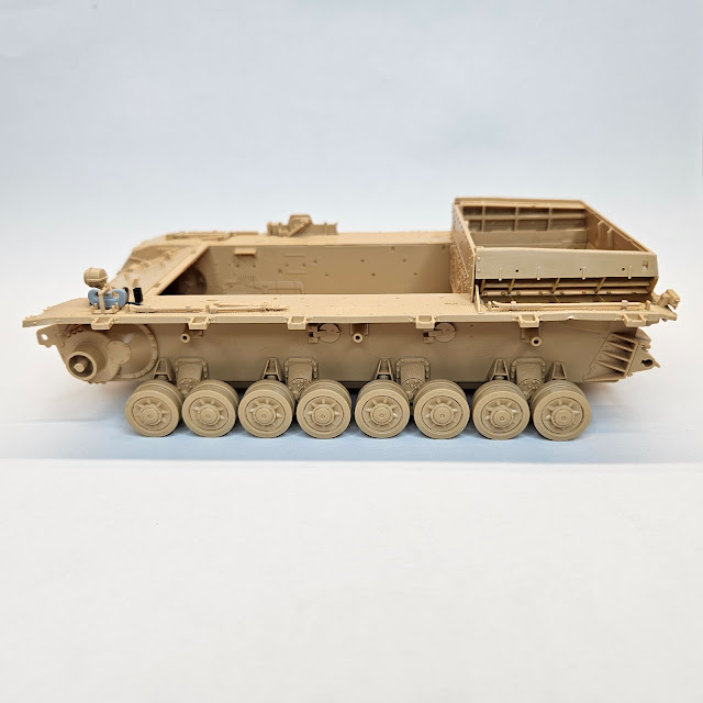
Progress before all but the smallest and most fragile parts are added. Tamiya rubber band tracks have been added just to keep all the wheels in line for the pic.


Thursday 14 March 2024

Rye Field Models RM-5033 1/35 2 in 1 Panzer IV Ausf J.


My first foray into building a Pz.IV Ausf J was as a dual build. It was an interesting comparison between a mid naughties Dragon kit, considered one of their best Ausf J's releases, and Border Models 2019 released BT-008 kit.

Using the well researched Panzer Tracts No.4-3 publication once more, I would now tackle Ryefield Models (RFM) 2 in 1 kit RM-5033.

This was released at the same time as their interior kit 5043 and uses similar flat pack engineering to create the Wanne (Hull tub). Kit 5033 allows you to build both a gun tank and an artillery observation tank. The instructions have you build the gun tank option with a three return roller Wanne, with extended side towing eyes. This is also how you are instructed to build up the gun tank in kit 5043. However, although not instructed to, you do get the choice to backdate the gun tank in both kits to a slightly earlier production variant, without some of the very last features. All the parts are available on the sprues.

This is a kit I have very much been looking forward to building.  It will be my first RFM kit and I have only heard goods things about them as a manufacturer. Although I understand purests have spotted some accuracy issues, the kit engineering is much lauded. So without further ado lets get started.

Upon opening the large box all the sprues are individually packaged and the instruction booklet looks nice and clear. There is also a small correction sheet, but this looks only applicable to their interor kit 5043. As already mentioned, in addition to the regular Ausf J gun tank, you can also build a Panzerbeobachtungswagen IV Ausf. J (Pz.Beob.Wg.IV Ausf.J). This was an artillery observation tank which started to be assembled on the Ausf J in April 1944. This is instructed to be built with a four return roller Wanne. Whether any were built on the later three roller Wanne I am unsure.

Checking over the sprues I was surprised to see a few parts covered in small traces of flash. They don't look too much trouble to clean up, but it is not something I expected to see on a kit so new. There are also a lot of mould stubs on the rear of parts. What RFM can be commended on is the positive placement of many of the more delicately moulded items to the sprue gates. Cleaning them up can be made much easier without sacrificing detail.


RFM offer an upgrade solution for super detailing. Set RM-2003 can be used both on this kit and their interior kit.


A little bit of Ausf J history

The Panzerkampfwagen IV Ausführung J (Sd.Kfz. 161/2) is the ninth and the last variant of the Panzerkampfwagen IV medium tank family. This variant was distinguished by numerous simplifications made to prior variants to accelerate production and conserve valuable materials. This last variant included replacing the single-speed turret traverse electric power drive with a two-gear manual traverse, in favour of extra space used for fuel storage. This was a last-ditch effort to increase Panzer IV production rate and compensate for tank losses.

Although both Nibelungenwerk (N-Werk from now on 😁) built 2980 units, and Vomag 180 Ausf J's, Vomag did build some of the very first vehicles. Due to the production run timescale the Vomag vehicle chassis numbers (Fahrgestellnummers) 86394 to 86573 would all have had both zimmerit (anti magnetic paste), the original muffler type exhaust and fittings for either type 1 or type 2 steel schurzen (spaced armour). So, due to some other prominent features this kit only represents N-Werk built vehicle variants. N-Werk built vehicles all had a unique application of three spare tracks fittings on the port side of the rear of the Aufbau (upper hull) up until around August 1944 but then switched to a six spare links arrangement on the starboard side. Only Drathgeflechtschurzen (wire mesh spaced armour) is offered in the kit so that would also mean both variants in the kit could only accurately represent builds produced from Sept 1944 if you decide to add them. Pz.Beob.Wg.IV Ausf.J (artillery observation tank) production started in April 1944 and although the kit instructs to add the Flammentor (Flame suppressing) twin vertical exhausts (fitted from August 1944), the option to backdate both variants with the older horizontal muffler is possible. The parts are available in the kit but will require additional work, as the location holes on the rear plate are only present for placement of the Flammentor type.


Options on the sprues to backdate both variants.

Options are limited, but as the kit shares sprues from their earlier released Ausf H kit there are a few parts which, although only called out in the instructions to be fitted to the Pz.Beob.Wg variant, could well still be relevant for a late 1944 built N-Werk built gun tank. For the turret, that includes the front plate (part E9) with the vision port still present. This change to delete it was not fully implemented out by wars end. As for Wanne (hull tub) production, the earlier tow coupling (parts K32, K33 & K92) and the later produced Ausf H front sidewall extensions (Parts K56 & K60) without towing eyes, along with rear tow hooks (parts K40 & K41) would have been relevant to all earlier production Ausf J's too.


The Ausf J used a 10./B.W Wanne and RFM offer this in a flat pack engineered design. A nice feature is the ability to open up different holes in the side plates to accept either four return rollers or the last production, bearing material saving three. These were introduced from December 1944. The gun tank option builds up with the last production Wanne feature of front and rear extended sidewalls with towing eyes (from Oct 44). Other late production Ausf J features were the introduction of simple single handles (from Feb 45) These replaced the original cast air intakes on each brake inspection hatch.  In December 1944 welded U brackets on the front of the Aufbau started to replace the bolted on lifting hooks. Both options are on the sprues.


The build

After inspecting all the contents and making a note of what might be available, but not actually called out in the instructions, I started with step one as per the instructions. As this was RFMs first Pz.IV kit, designed along with their interior kit released later that year, the lower hull is built up in sections to allow for additional interior detail. Any opening hatches come as separate items which is to be applauded. All the flatpack lower hull parts erect positively and cleanly and although there is no internal bracing to fit at this stage it all lines up straight and true. It is worth noting that due to the tight friction design of the sidewall to floor plate connection, some pressure does need to be exerted whilst the glue bonds, to ensure that both pieces sit completely flush along their whole length.


 Flatpack 10./B.W Wanne assembled with front towing eye extensions and sprocket housings fitted.


The option to have the main road wheel bogies moveable by snipping away a small tab is a welcome feature, and all the wheels have poly caps. Pay attention as the idlers use Poly Cap 2 which is shorter. Poly caps when they work; I'm looking at you Border Model, is something I personally like. This system of wheel fitment is extremely useful if you like to paint your running gear separately. A design that allows the sprocket to rotate without glue is always a bonus if you have to resort to guiding aftermarket tracks on, especially where there is limited room below the track guard.  Due to snug fitting poly caps both sprocket, idler and roadwheels can all be fixed safely in position without the need for glue.


 Moveable bogie suspension


One small anomaly found in this build stage is found on the outer face of the cast idler wheels. They have a small lip on both their inner and outer rim which wasn’t present on the real thing.  This will require removal.


 The lip present on the right and sanded off on the left. The central greese nipple will need to be replaced if you use a wide sanding stick as I did.


Lower hull assembly with bogies. I have fitted both front and rear extensions with towing eyes and the track pin return plate to represent a 1945 production Ausf J.


The interlocking glacis transmission plate fits snugly between both hull side plates. I did dry fit this to aid spacing before the Wanne assembly fully cured. As mentioned, the option is there to choose either the armoured air intakes or the simple handles on the transmission hatches. Unlike some other manufacturers RFM only provide plastic spare track brackets. These are a little bulky and would be far better represented in photoetch but they are usable. Their spacing is marked out via witness marks on the transmission plate, but they are obviously only for fitment for the RFM spare tracks. If aftermarket tracks are being used, spacing will need to be adjusted accordingly. 


 Interlocking transmission plate with late production single trans hatch handles fitted


The next steps involve populating both track guards with all the pioneer tools and fittings. You are also instructed to assemble and fit the two part engine cooling louvres. These attach to the track guards before the Aufbau assemby is constructed and added. Again, everything fits extremely well. Unfortunately the C hooks were a bit of a disappointment. They both had two prominent and visible sink holes on one face and will require filler. I simply replaced one from the spares bin. I also sourced a 3D printed empty fire extinguisher holder.


The track guards attach to the Wanne side plates positively due to cut outs, and once in place the engine compartment firewall panel can be slotted down onto the Wanne floor, effectively trapping both track guards in place. This will also provide support for the top plate of the Aufbau once fitted. The Aufbau rear plate can now be fitted. 


 Flammentor exhaust fixing location detail on the rear plate.

Before committing to final fixing, the Aufbau sub-assembly was test fitted to the Wanne sub-assembly. This locates precisely into slots into both the transmission plate and track guards, and into cut-outs on the rear face of the rear plate. This will then rest on the firewall panel and engine cooling louvres.


Front detail on the Aufbau sub-assembly. The later production feature of square shaped bullet splash guards for both hatches are correctly represented.


Test fitting on my build resulted in the Aufbau top plate sitting a millimetre too high against the rear plate meaning it did not sit flush as it should. The offending items appeared to be both engine cooling louvres sitting a fraction too high. The Aufbau top plate angles down slightly just behind the engine hatches onto the top of the louvres and this is where it was fouling. An armoured outer plate part then covers the top of the louvres and should neatly butt up against both the top and rear plates after the two sub-assemblies are connected. The top plate was also not engaging down onto the firewall, which it obviously should. The only solution was to shave a small amount of material off the top of the louvres.


Slowly removing a little plastic at a time from the top of the engine cooling louvres, the hull top panel finally fell into place. The engine deck hatches, and the remaining fittings could now be added.


With that little fitment conundrum behind me it was time to move onto the turret.

The comprehensive gun breach and cradle parts are exactly the same as on their interior kit. Although not called out, a few other interior items from this kit can be found on various sprue trees. Unfortunately, the rotating turret floor moulding is missing crucial bracket parts that would enable you to add it to the turret surround. However, with what is available, there is still plenty of detail to eyeball, shoud you model any turret hatches open.

It would have been nice to see a metal barrel although the slide moulded one is easily cleaned up to remove the very faint seam line. You do get a choice of three plastic muzzle brakes. As of writing, looking on the Scalemate’s site, I don’t yet see a metal barrel option available for this kit!

The upper and lower two-part turret mouldings are nicely engineered with weld line detail hiding the joint. The gun breach and cradle fixes to the lower part so you can paint the interior easily enough before joining the turret halves together. Although not called out for on the gun tank option, it would also be appropriate to fit the front panel with the vision port.  If the instructions are followed and the vision port delete panel is chosen the four screw head detail moulded onto the turret roof, above and behind where it sat need to be removed.


One small anomaly I found in step 24 was that part S17 (the Nahverteidigungswaffe cover) is orientated in a fixed position on the turret roof. In reality it could rotate 360 degrees from inside the turret so can be fixed in any position. Repositioning it if you wish is simple to remedy. The part has two pips underneath, the larger one is to fit into a 1mm hole that you have been instructed to drill out in step 23. The solution is to snip off the larger pip and simply choose your orientation. The smaller pip sits centrally and the cover hides the 1mm hole that you drilled anyway.

The turret schurzen are accurate for a N-Werk built vehicle in so far as they have the correct brackets and appropriate bolt fixing location points to both the turret and the panels. N-werk vehicles had a unique feature and differed to the earlier Krupp built vehicles. The side plates of the schurzen were mounted 50mm further forward which changed the door position and different support brackets were used. This also meant different mounts held the splash guard protector for the cupola base. The exposed bolt head pattern on the exterior of the front schurzen panel is the visible clue to the manufacturer. The middle bolt will be rearward of the upper and lower bolts on all N-Werk vehicles.

Unfortunately, as soon as I snipped my turret schurzen panels off the sprue gates it was apparent that both the front sections bowed inwards quite badly. I soaked them in warm water and left them overnight under a weight, but they simply sprang back the next day when the weight was removed! I am hoping that the fixing of the brackets to the turret will straighten them out. 


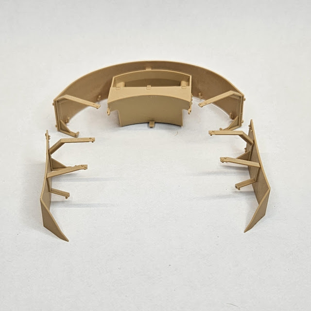
As with the hull schurzen the turret brackets were fixed to the panels first to get a nice clean fitment. As there is very little room between both the rear curved panel and the turret bin these areas will require an airbrushed shadow coat before final fixing to the turret. Photoetch storage trays at the rear of the schurzen are added by way of either plastic or PE brackets. As they would be hardly visible, I opted for the more durable plastic option and thinned them down.

The cupola assembly is a comprehensive model in itself.  It contains a myriad of parts, but they all fit perfectly, and it looks exquisite once built up. You get two main cupola contruction options; one to build up with the armoured visor covers permanently open, and one so the covers simply slot in and can be left moveable.


Tracks

RFM offer individual links together with a fitting jig. They are an appropriate type for the vehicle. Along with this out of the box solution I had quite a few other options. First up I had the three-return roller link and length tracks leftover from the Border kit. In addition I also had two 3D printed aftermarket sets.  T-Rex and QuickTrack. As I hadn't yet tried them, I finally opted for the QuickTrack snap fit set.

These are type 7 links and come in two bags for both left and right fitting. A small bag with a few open links and wire, to which you can thread through to close a completed track loop is also included. Both runs were built up in an alarmingly quick 20mins. They do indeed simply snap together and are far more robust than they look once assembled.


The idler wheel axle does have a small locating tab to fix it in one position inside the lower hull housing but that is easily removed if you wish to adjust it. Even with the tab left in place both my completed runs fitted perfectly. The top run doesn’t sag over the return rollers as naturally as the T-Rex type links with pins, but that is simply due to the QuickTrack design having more friction in the snap nature of the connection. It is not an issue as it only takes a little manual manipulation for them to look the business.

Next up is the Drathgelflechtschurzen (mesh space armour). In these steps you can build the kit up without the tubular rails altogether, by simply adding blanking plates to the upper hull. To replicate this option accurately you would have to drill lots of very small holes in the track guard side profiles where the lower brackets would have attached. That will involve a very fine drill and a very steady hand!

The tubular top rail provided only comes with cut-outs for the mesh panel brackets. There is no complete rail without any cut-outs to provide an alternative empty rail. If you wanted to display the odd mesh panel missing, you would have to fill the cut-outs. I notice RFM in one of their CAD images simple show the brackets attached to the rail where a central mesh panel is missing which is a little strange. In reality the bracket was welded or bolted to the panel and clipped over the rail. The upper brackets connect the tubular rail to the rear of the schurzen panels. The lower brackets connect the rear of the schurzen panel to the track guards. These lower brackets are in two parts to allow for two fitment postitions. This was to enable the use of wider Winterketten/Ostketten tracks. The upper rail brackets is in one part but has two fixed positions whereas the track guard brackets had to be adjusted to sit further out to accept the wider track type. The outer portion of the bracket needs to be positioned horizontally to clear the wider track type. In step 17 these are only shown fitted in the vertical position to accept the regular tracks included in the kit. The real bracket was hinged but you need to decide which perminant option you want beforehand (unless you fancy drilling and pinning all eight brackets!)


The middle mesh panel looks a little out of alignment in the pic below, but that is due to the rails being dry fitted to the hull.


Rather than attaching the tubular rail brackets to the upper hull as instructed, I employed a similar method as I had with a previous Ausf J kit. As the connection point on the bracket requires work to get it to sit cleanly in the tubular rail cut-out, I reckoned it a whole lot easier to get that cleaner connection by attaching the brackets to the rail first. Checking as I cleaned up each bracket that it was the correct fitment to the hull, I ended up with a sub-assembly that I could test fit to both upper hull and track guard, to assure it all aligned correctly. I then dry fitted both rail and bracket assemblies, so they fully cured overnight in exactly the right position.

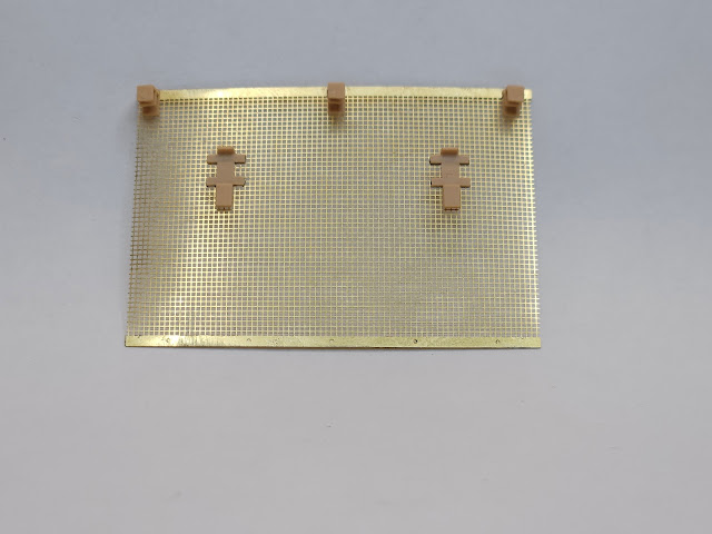
The mesh panels themselves are in photoetch with predrilled holes to align perfectly to the lower plastic brackets. Plastic is used again to represent the upper brackets. These are as thin as you could possibly expect the mouldings to be without being overly fragile. The PE mesh panel weavepattern looks really good, and they are convincingly thin. The upper brackets attach to shallow cut-outs on the top of the mesh panel so as to align with the cut-outs on the tubular rail. Each panel is framed on the outside, represented by PE strips with bolt head detail. These then line up and are fixed to the outside framework of each panel. TBH most of the work during these steps involves cleaning up all the PE strips as they are very thin and prone to bending. 


The two lower plastic brackets fit through the mesh panel precut holes and are fixed to PE locking strips on the outside which is nice and simple to achieve. The last step is to add the upper rail brackets to the top of the panels.


Compared to the Dragon and Border kits I built in an earlier blog, I think RFM have improved on both the engineering and the materials used for these mesh screens. Parts fitment is superb, and the scale appearance looks very convincing.