Cargo bed
The wooden framed cargo bed is attached to the chassis via three beams which are secured with U-shaped shackle pins. Access to insert the shackle pins is extremely difficult if you plan to keep the cargo bed, frame and beams separate, but there is an alternative build process to those in the instructions worth considering as I discovered.
This option is to just attach the cargo beam parts F17, F26 and F27 (step 8) once the chassis is built up, leaving you to attach the remaining frame parts as per step 7 to the cargo bed. This way you can add the U- shaped shackle pins but keep the cargo bed separate.
If you do use this method before attaching these three beam parts to the chassis be sure to dry fit them first when building up the remaining frame parts in step 7. This way you can be sure both the cargo bed frame and the beams will mate nicely together. This alternative method of construction also makes life a whole lot simpler when adding the cab with the steering column attached. Likewise, propshafts and exhaust parts are easier to position with access from both above and below.
My kit had particularily bad seam lines on a lot of the cargo frame parts, so ensuring they are cleaned up nice and square will allow for a much better fitment.
There were zero injector pin marks on any of my wooden deck parts although there is a seam line around the outside which will require clean up. Slighty sanding and widening the inside of all the side frame brackets will also aid a better fit when it is time to mount the cargo bed sides. The various wooden parts have markedly different wood grain patterns and textures and are also moulded on both sides. The detail of all the brackets and other fittings is excellent, and the separate latches for the drop sides are a great detail, The only omission is there are no tie down hooks for the tarpaulin. These are items that would benefit from adding.
Chassis
The chassis is a multipart construction. Care is needed to make sure everything lines up nice and square before grabbing the cement. There are prominent seam lines on every part called out in step 10 so I had to ensure they were cleaned up well to avoid miss-allignment of the chassis legs. If you don’t get a nice square fit with all these parts in both the vertical and horizontal planes, it will likely complicate further connection of parts to the cargo body and cab. Test fitting of all the crossmembers is crucial as they all need to fit into slots in the chassis legs to ensure they sit parallel. Time spent on cleaning up parts will eventually reward you with a nice tight-fitting assembly.
Prominent pin marks were filled with putty.
Although the instructions call out for them early on, some of the more delicate parts such as part C34 do not need to be attached to the chassis in the steps called out for. These can easily be attached once assembley of the main frame is completed as it avoids the possibility of damaging them whilst handling.
Initial stage of chassis assembly following the instruction sequence.
Exhaust & propshafts
As per the instructions the exhaust is far easier to attach before the rear axle is fitted. How do I know that? Cos numpty here left it off by accident! Another point worth mentioning in step 13 is the fitment location of the exhaust silencer to the inside of the chassis. It is not at all clear in the instructions how this is attached as there are no locating points on the chassis. The rearmost exhaust bracket location points are easier to work so you then get an approximate location of the silencer. There is a chassis leg shackle pin that will interfere unless you have already positioned it in the correct orientation.
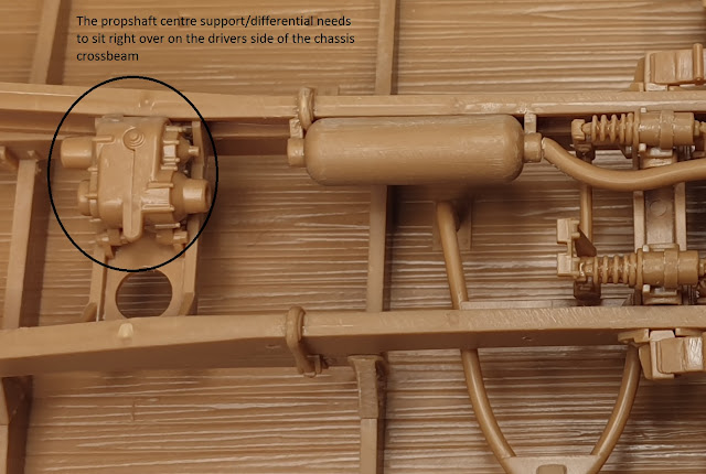
In step 14 ensure the prop shaft centre support (parts E15 and E16) sits correctly. There are two locating tabs on the crossbeam but the part needs a firm push in to locate it. The part should sit right over to the drivers (left) side of the beam. This way all the propshafts will line up correctly.


No comments:
Post a Comment